Help Center Permit
Customizing Electrical and Permit Settings for Permit Plan Set Generation
Published on 19 Mar 2026
Solargraf provides a range of customization options under Electrical and Permit Settings, allowing installers and designers to tailor their plan sets according to project needs and company standards. These configurations streamline permit plan set generation, improve accuracy, and ensure compliance with NEC and site-specific practices.
Users can access these settings by navigating to:
Company settings → Design → Electrical and permit settings
The configuration options are divided into two main sections — Electrical settings and Permit settings — each designed to simplify workflows and enhance flexibility during plan set creation.
Electrical settings
Solargraf’s Electrical settings section includes 5 key customization fields:
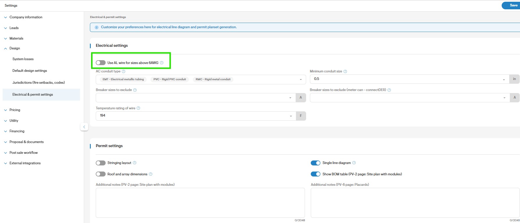
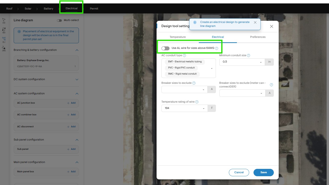
Use aluminum wires
This setting allows users to enable usage of AL wires for wire sizes above 6AWG. It allows users to switch from the standard all-copper wiring to a new setting that automatically uses copper for wires up to 6 AWG cross section and aluminum for wires larger than 6 AWG cross section.
How to Configure:
- Go to Company Settings → Electrical and Permit Settings
- Toggle ON the Use AL wire for sizes above 6AWG.
- Once saved, the setting applies to all new projects by default but can be overridden at the individual project level in the Electrical Design tool.
AC conduit type
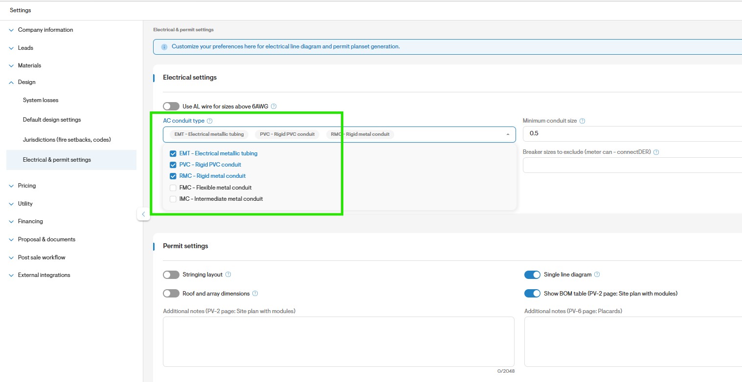
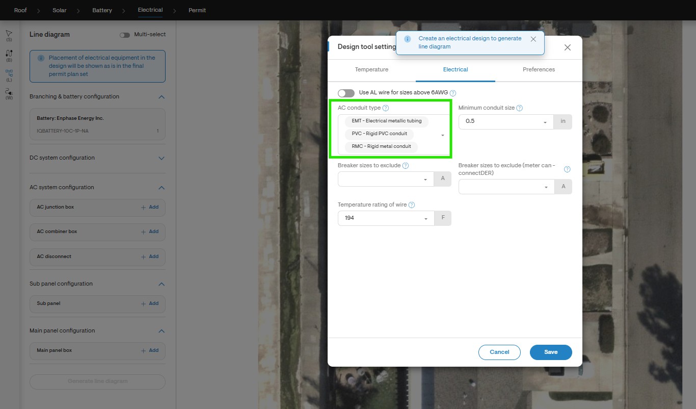
This setting allows users to specify the preferred conduit for the AC wire installation, aligning with your best practices, to reflect in wire details section of electrical line diagram and wiring calculations page of permit planset.
How to Configure:
- Go to Company Settings → Electrical and Permit Settings
- Default EMT, PVC and RMC are selected.
- Update the ones needed.
- Once saved, this setting applies to all new projects by default but can be overridden at the individual project level in the Electrical Design tool.
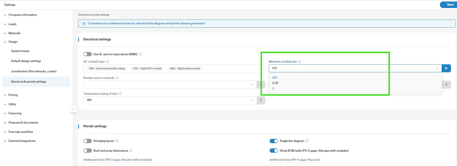
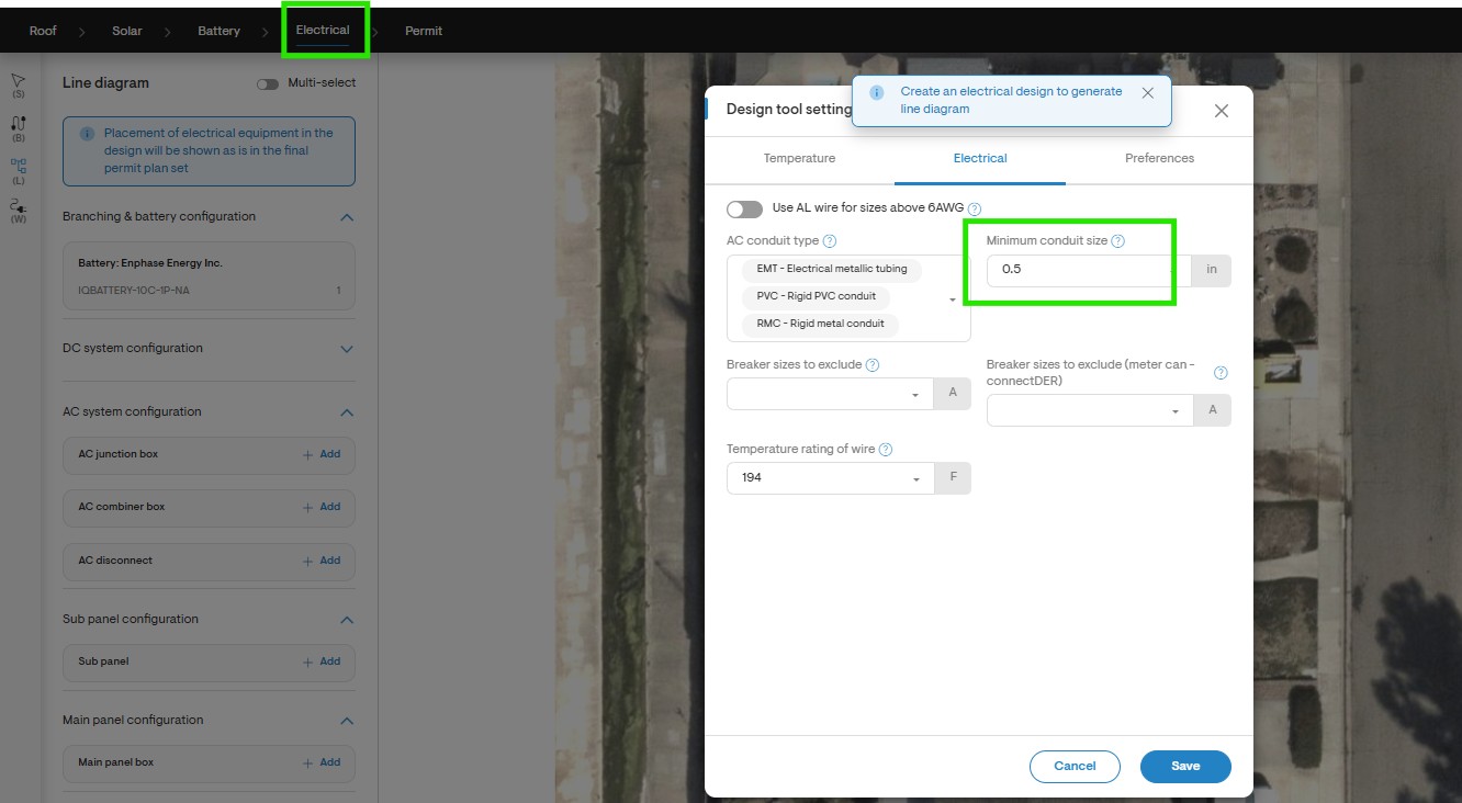
Minimum Conduit Size for Wire Calculations
Users can define the minimum conduit size for wire calculations, ensuring consistency with internal standards or local regulations. This value will be reflected in the Wire Details section of the SLD and the Wiring Calculations page in the permit plan set.
How to Configure:
- Go to Company Settings → Electrical and Permit Settings
- Define the minimum conduit size (default: ½ inch).
- Options like ¾ inch or 1 inch can also be selected.
- Once saved, this setting applies to all new projects by default but can be overridden at the individual project level in the Electrical Design tool.
Breaker Size Exclusion in SLD Generation
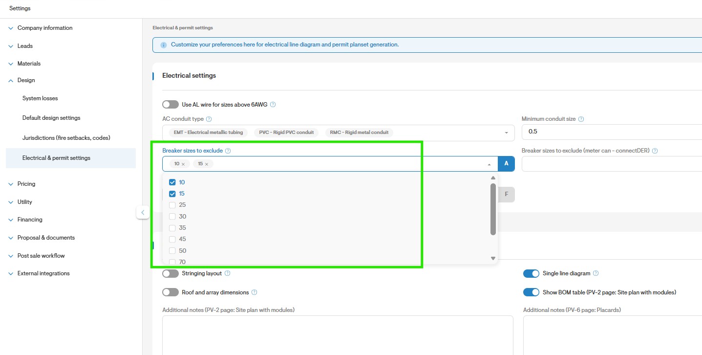
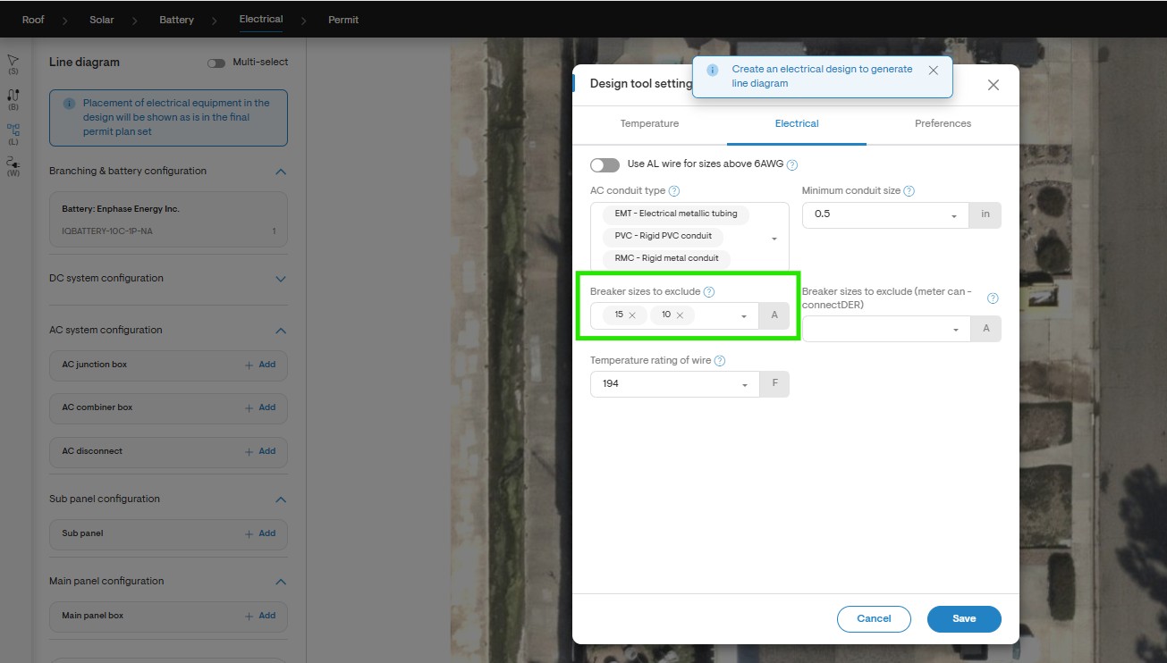
This setting allows users to exclude specific breaker sizes when generating single-line diagrams (SLDs). For example, if a 35A breaker is unavailable in the market, users can select it in the exclusion list, and Solargraf will automatically use the next available breaker size (e.g., 40A) while recalculating wire sizes as per NEC standards.
How to Configure:
- Go to Company Settings → Electrical and Permit Settings
- Select the breaker sizes you want to exclude (multi-select supported).
- Once saved, this setting applies to all new projects by default but can be overridden at the individual project level in the Electrical Design tool.
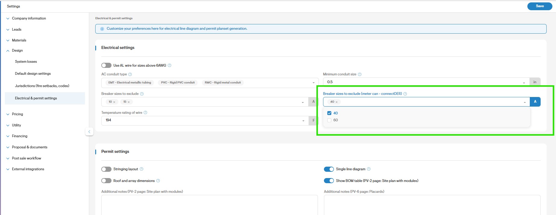
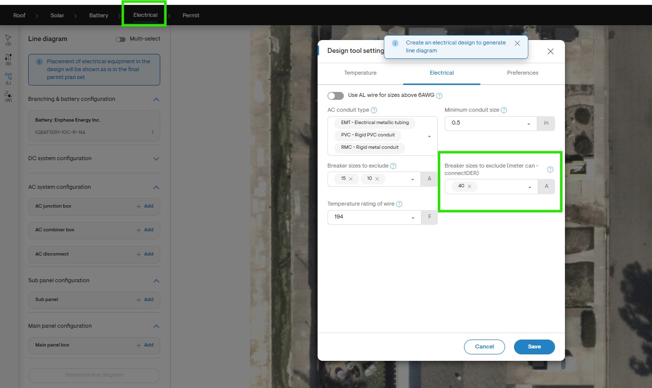
Breaker Size Exclusion (meter can - connectDER) in SLD Generation
This setting allows users to exclude specific breaker sizes when generating single-line diagrams (SLDs). It is applicable only when the interconnection tie-in method is set to Line-side connection (meter can - connectDER).
How to Configure:
- Go to Company Settings → Electrical and Permit Settings
- Select the breaker sizes you want to exclude (multi-select supported).
- Once saved, this setting applies to all new projects by default but can be overridden at the individual project level in the Electrical Design tool.
Setting Wire Temperature Rating (75°C or 90°C)
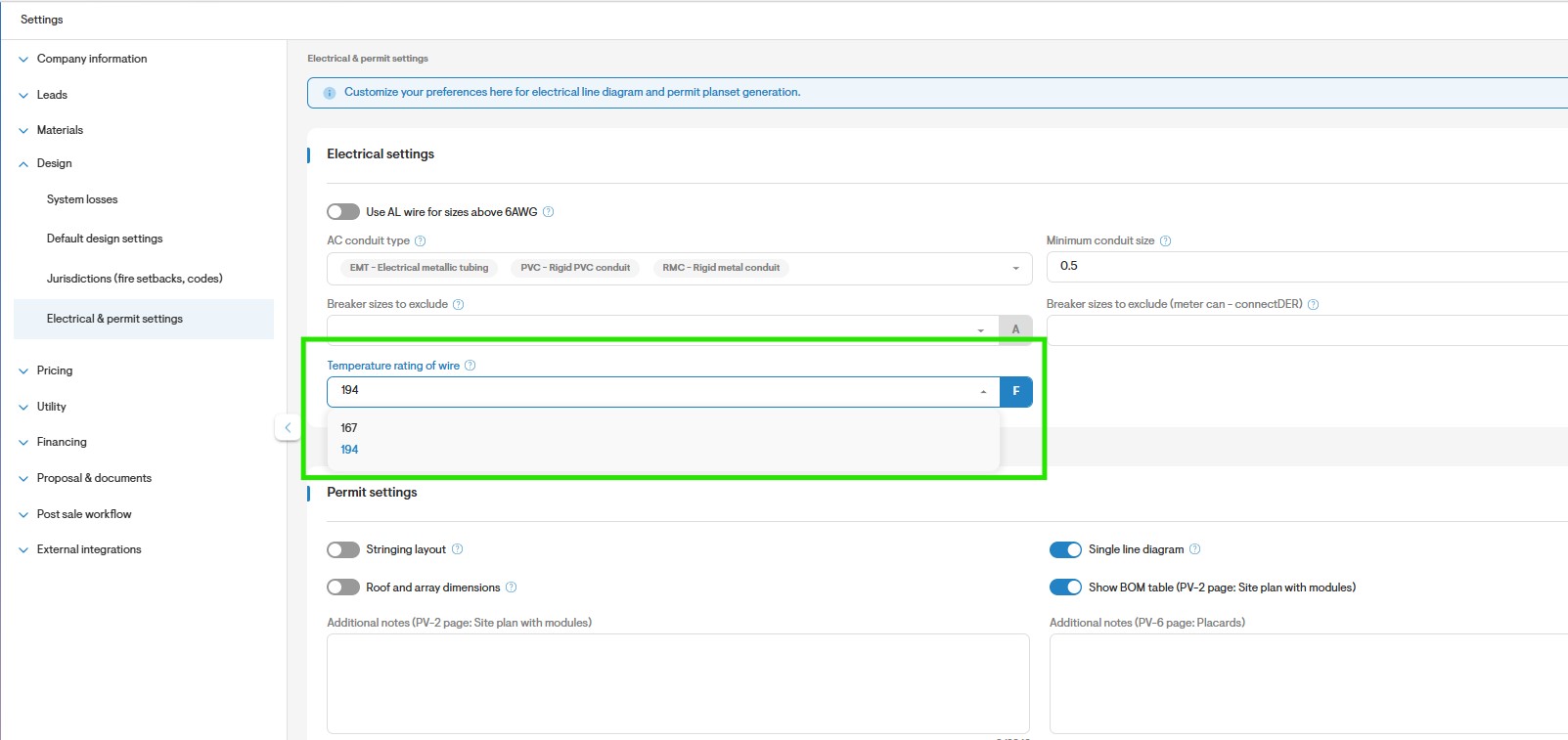
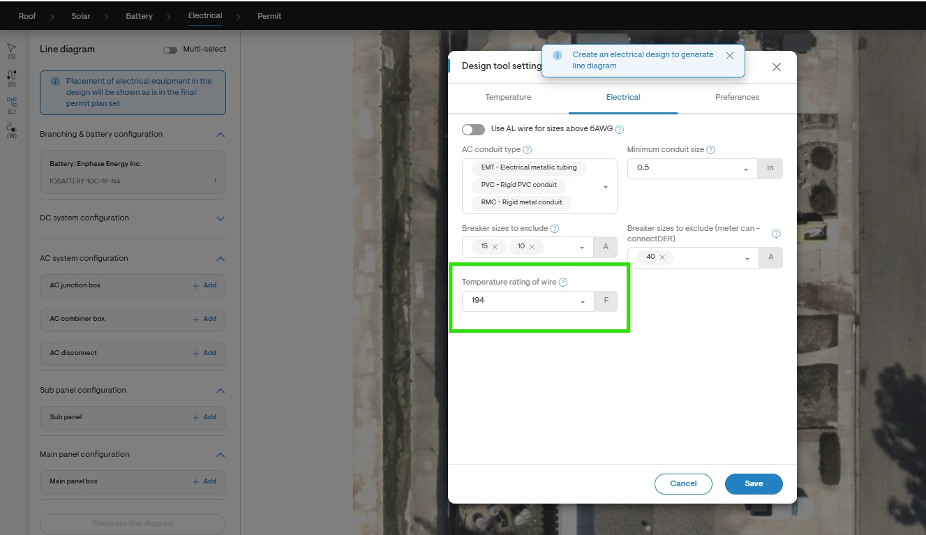
This setting helps ensure that designs comply with specific site conditions and internal best practices. Users can define a default wire temperature rating (75°C or 90°C), which directly affects wire sizing and ampacity calculations.
How to Configure (Company-Wide Default):
- Go to Company Settings → Electrical and Permit Settings
- Choose the desired wire temperature rating (default: 90°C).
- Once saved, this setting applies to all new projects by default but can be overridden at the individual project level in the Electrical Design tool.
Permit Settings
Under Permit Settings, users can customize how additional notes and contractor signatures appear on specific pages of the permit plan set. These fields allow for added clarity, personalisation, and automation during the final plan generation.
Permit adders
User can add additional pages/section to appear in the final permit planset generation. It includes:
- Stringing layout: schematic illustrating the wiring between solar panels to form strings/branches.
- Single line diagram: showing the solar system's electrical components and their interconnections, including storage if applicable.
- Roof and array dimensions: illustrates reference dimensions of the PV array from the roof edges to support the installation crew.
- Show BOM table (PV-2 page: Site plan with modules): showing comprehensive Bill of materials as per the design.
How to Configure:
- Go to Company Settings → Electrical and Permit Settings
- Toggle ON/OFF the required adders as per the need
- The adders will apply to all new projects, but you can override them per project at the permit checkout stage.
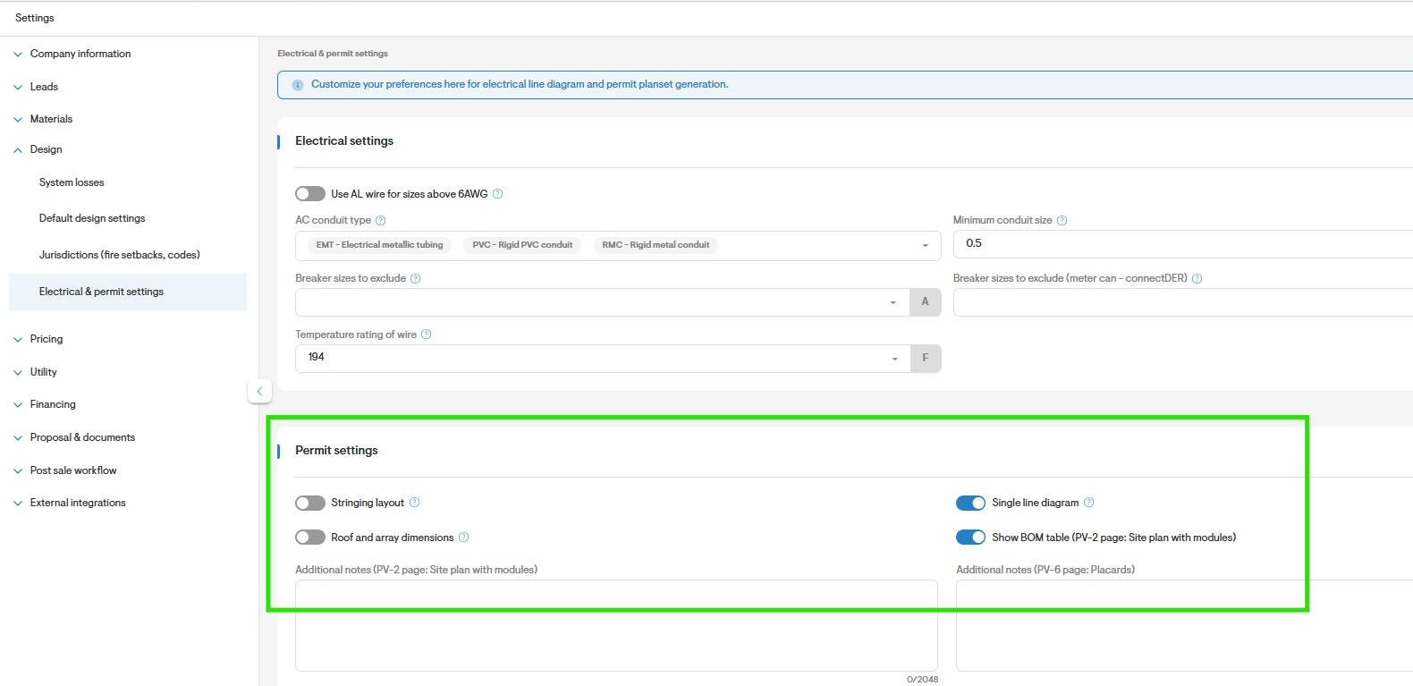
Electrical and permit settings - Permit adders.
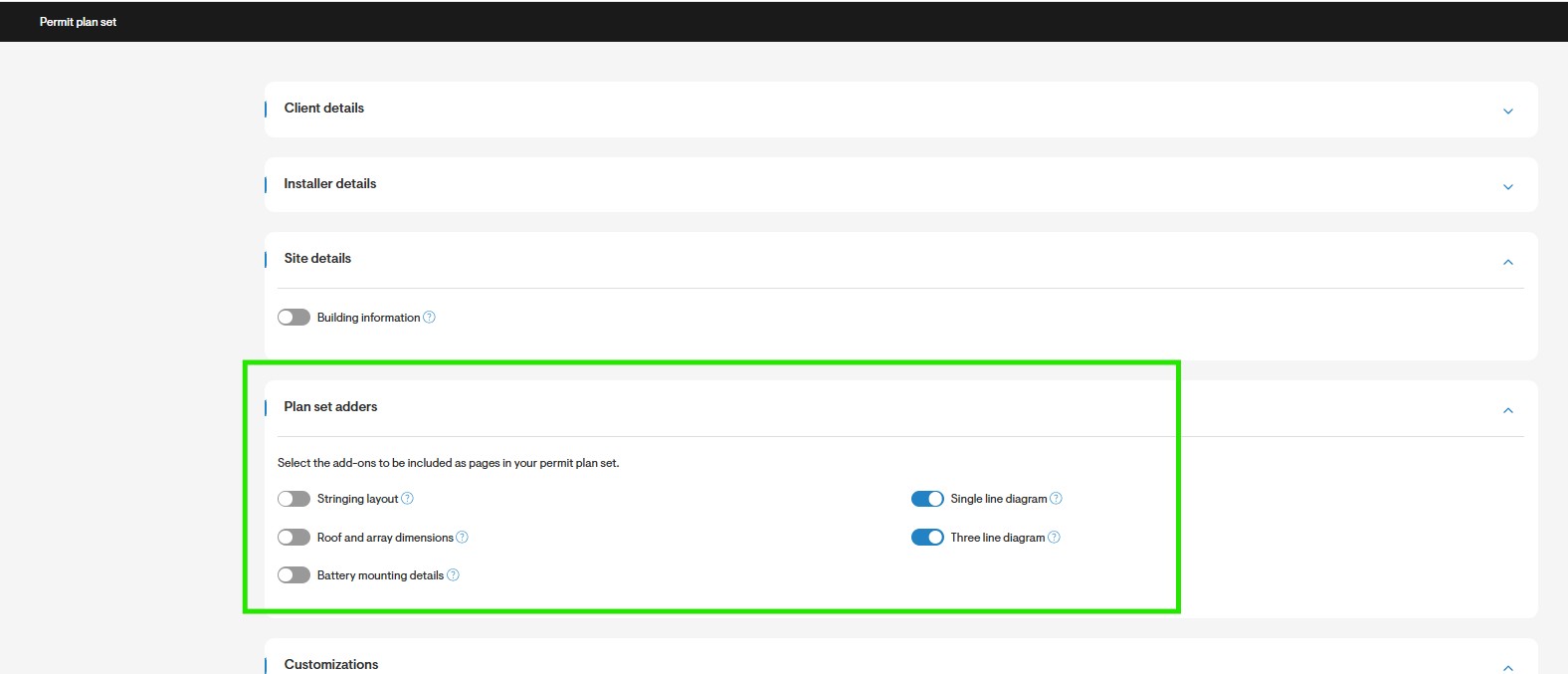
Permit checkout page - Permit adders at project level.
Additional Notes on PV2 Page (Roof Plan with Modules)
Add custom project notes or installer-specific information directly on the PV2 page of the permit plan set.
How to Configure:
- Go to Company Settings → Electrical and Permit Settings
- Add your custom notes for PV2. (Default is empty.)
- The notes will apply to all new projects, but you can override them per project at the permit checkout stage.
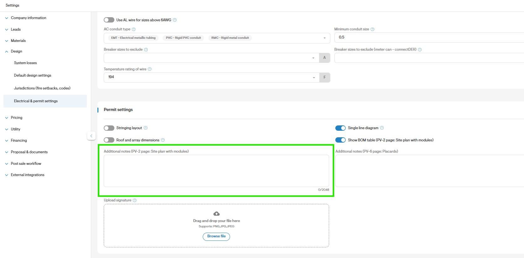
Electrical and permit settings: Additional PV2 notes.
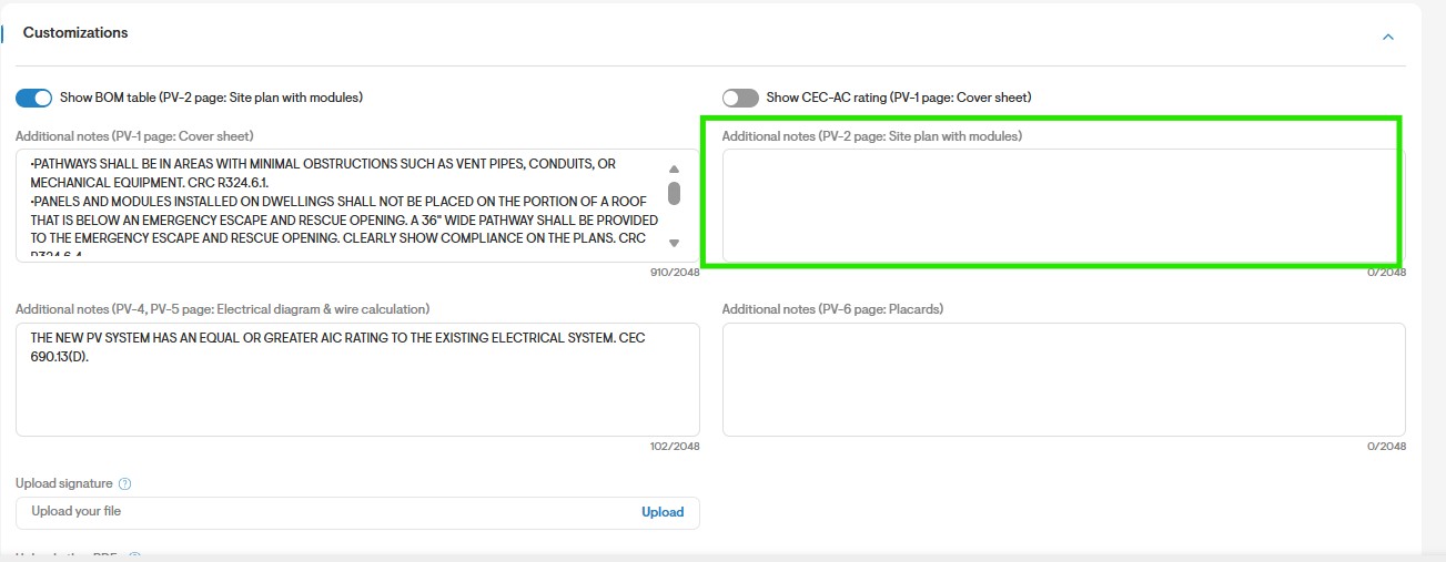
Permit checkout page - PV2 page notes field at project level.
Additional Notes on PV6 Page (Placards Page)
Users can add supplementary notes on the PV6 Placard page to appear after Solargraf’s automatically generated text.
How to Configure:
- Go to Company Settings → Electrical and Permit Settings
- Add your custom notes for PV6. (Default is empty.)
- The notes will apply to all new projects, but you can override them per project at the permit checkout stage.
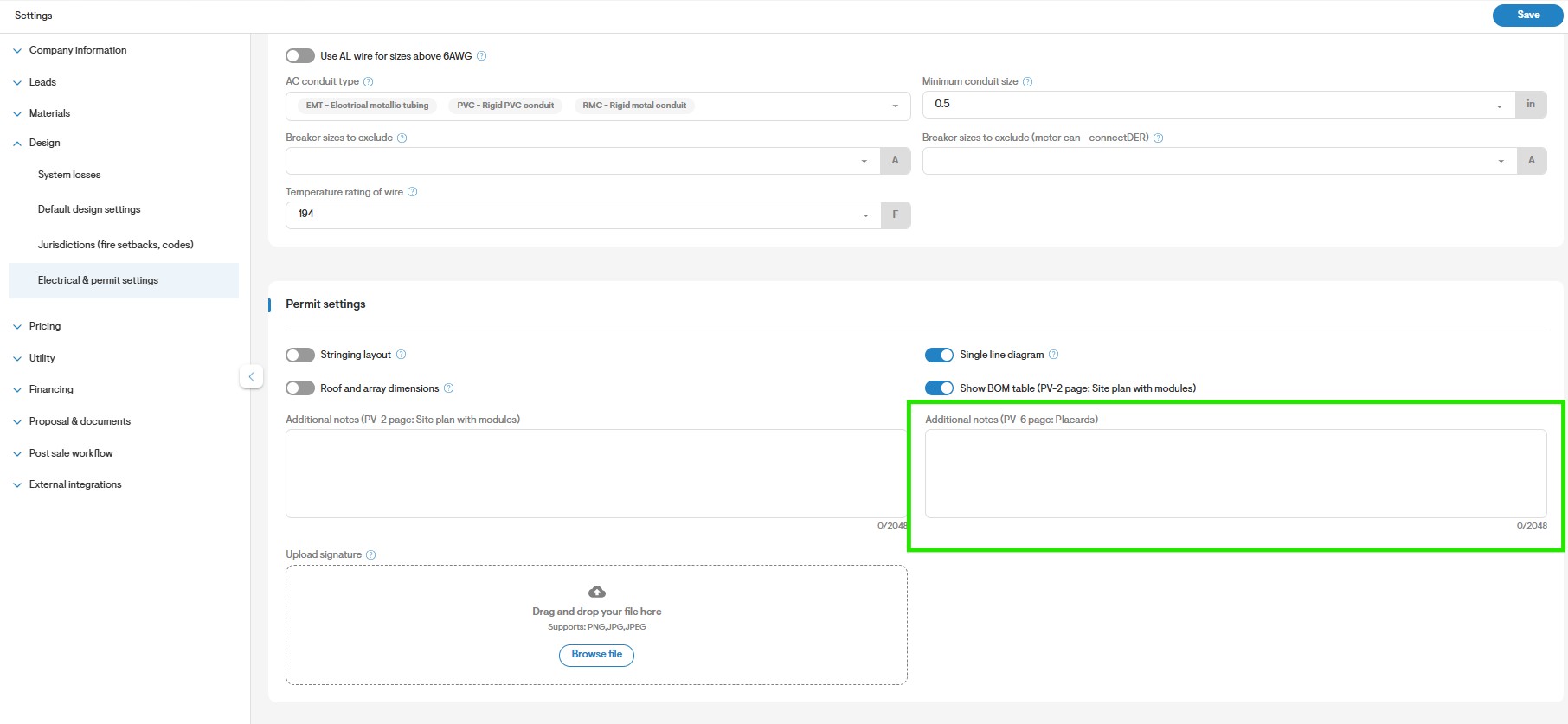
Electrical and permit settings: Additional PV6 notes.
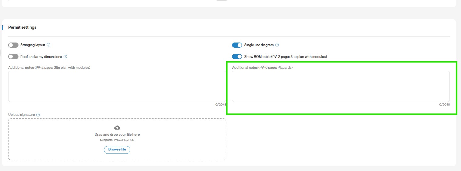
Permit checkout page - Additional PV6 notes at project level.
Automate Signature
This feature automates the inclusion of the contractor’s or designer signature in the permit plan set — saving time and ensuring a professional finish to every generated plan.
How to Configure:
- Go to Company Settings → Electrical and Permit Settings
- Upload the contractor/designer signature file. (default empty)
- The signature will apply to all new projects, but you can override them per project at the permit checkout stage.
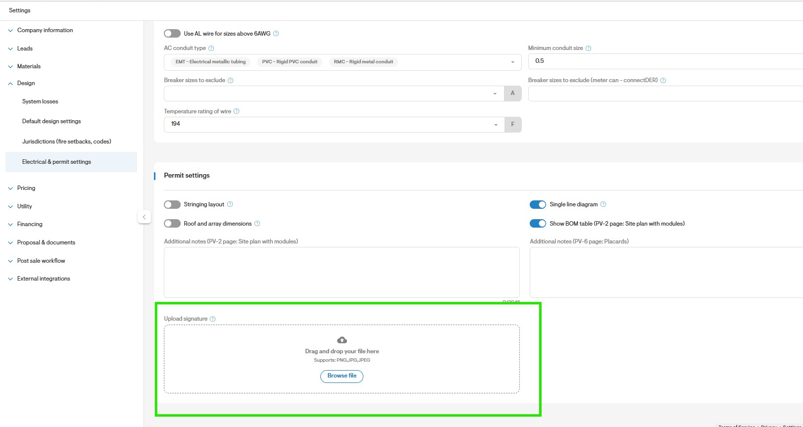
Electrical and permit settings - Upload signature.
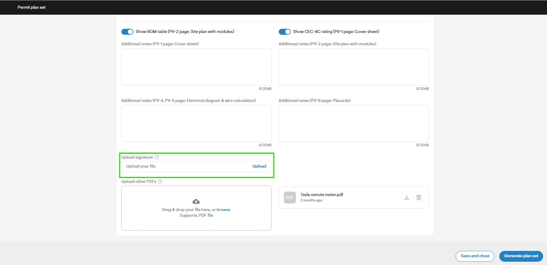
Permit checkout page - Upload signature at project level.
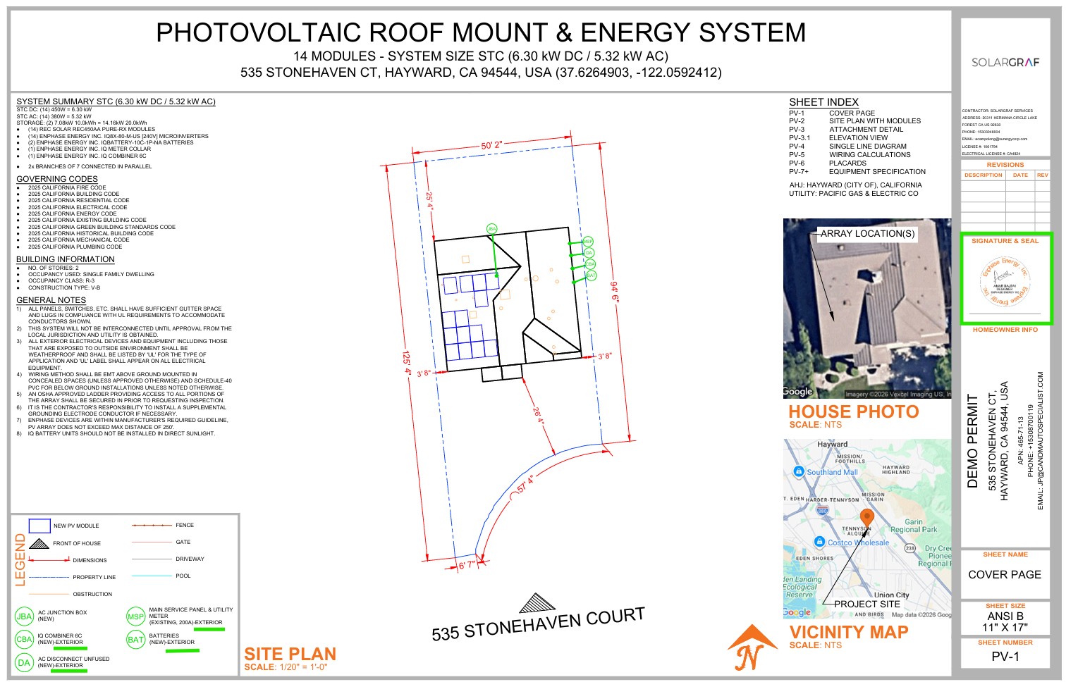
Permit Planset - Signature
Additional customizations
Beyond the standard Electrical and Permit Settings, Solargraf now offers even more advanced customizations to enhance the accuracy, automation, and professionalism of your permit plan sets.
Property Line Adjustments
The new Property Line Adjustment feature allows users to view, move, and validate property boundaries to prevent design conflicts.
Steps:
- Go to the Permit Design tab — property lines appear as blue hashed lines.
- If any overlap with the roof, they highlight in orange with a warning.
- Click the Property Lines icon → Move Property Lines and drag to reposition.
- Use Set to Default to revert changes.
- Extremely large property lines appear only on the final plan set.
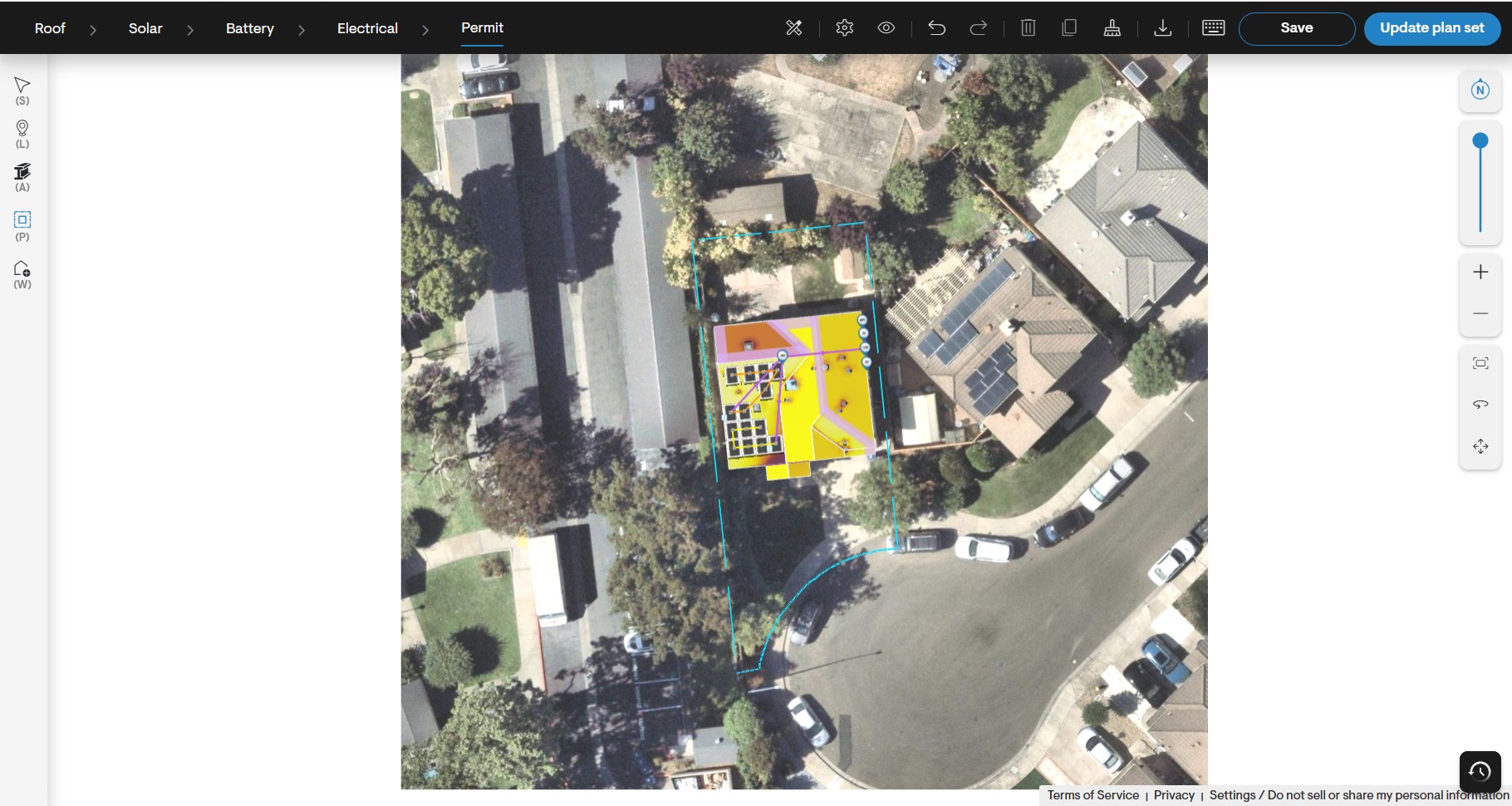
Permit design - Display property lines.
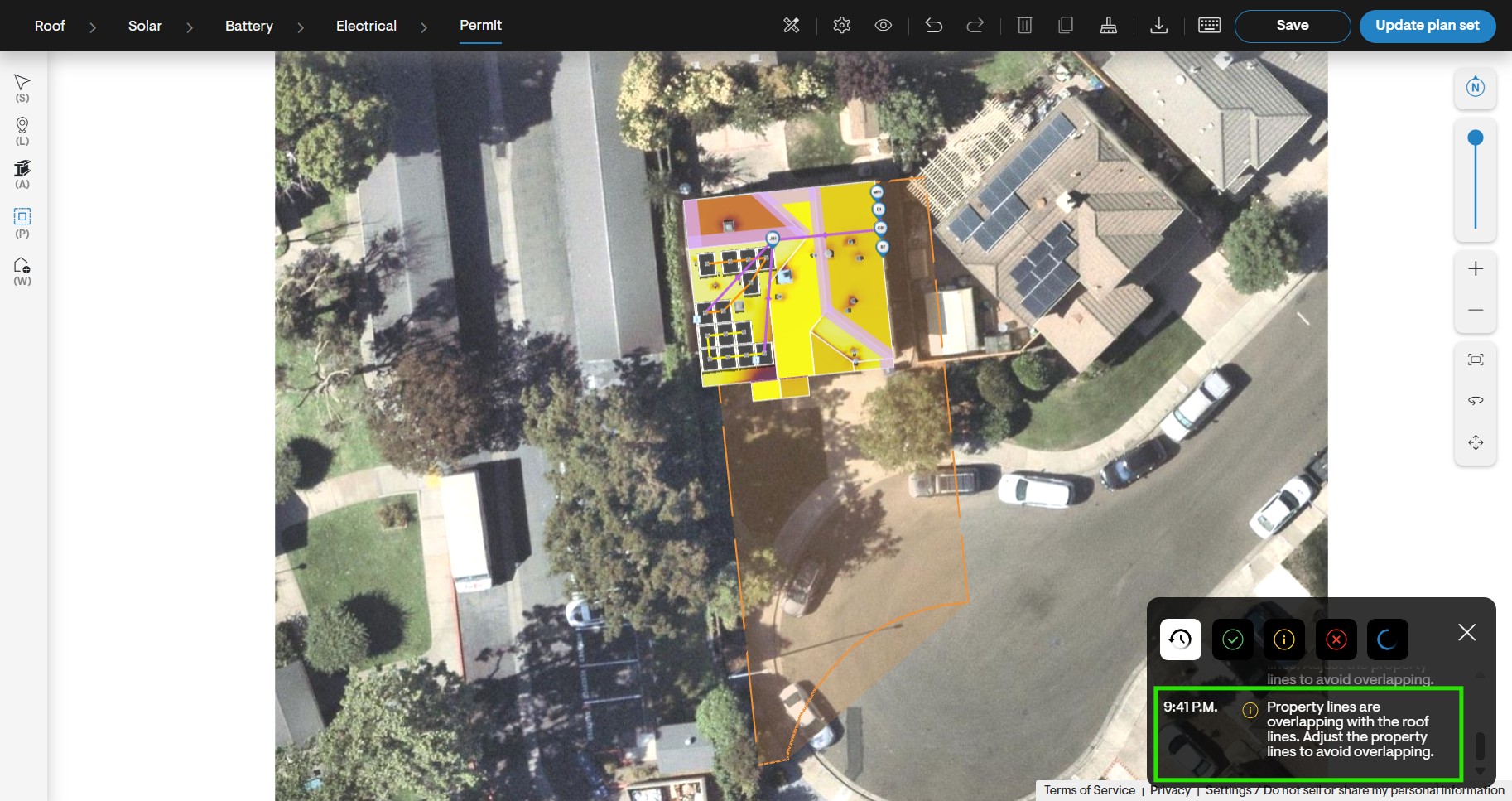
Permit design - Property lines overlapping with rood lines.
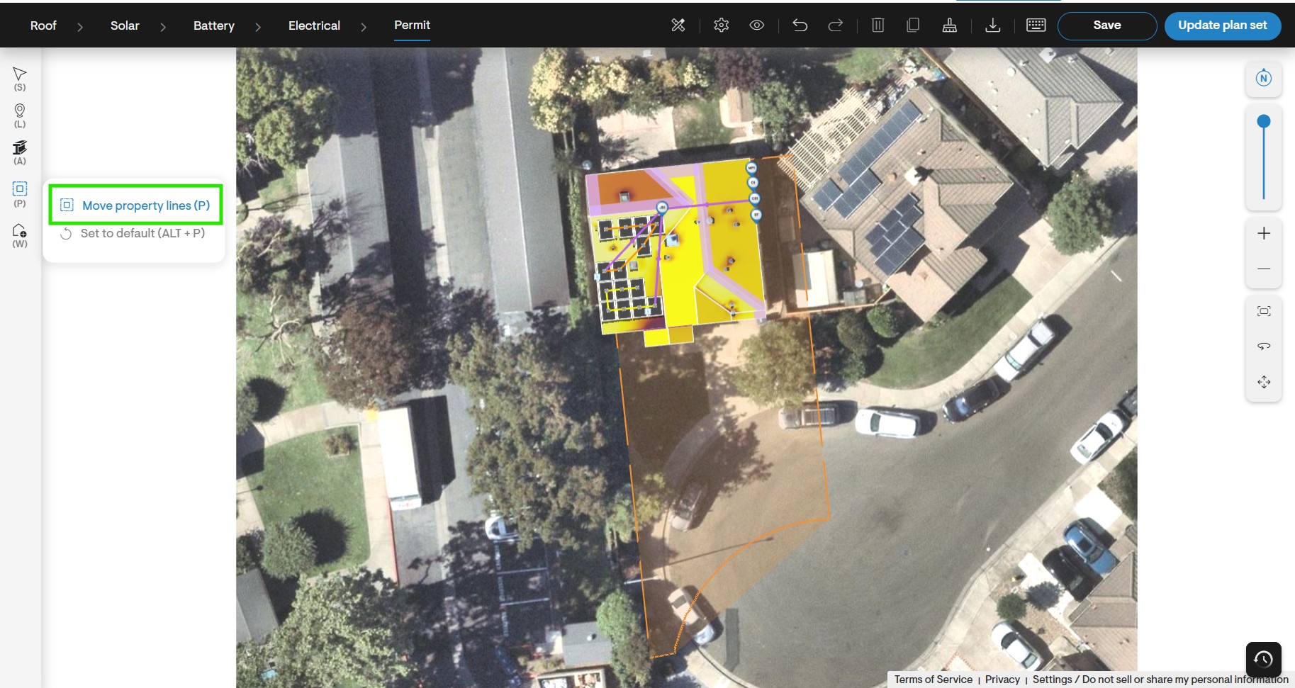
Permit design - Move property lines feature to