Help Center Electrical Design
Solargraf Electrical Design Tool: A comprehensive guide
Published on 5 Mar 2026
Creating solar and battery designs in Solargraf is a straightforward process. Here's a quick guide to common design setups, from simple PV systems to complex full-home backups.
The Electrical Design Tool (EDT) in Solargraf is a robust feature that assists users in creating electrical circuits, placing components, and generating professional single-line diagrams (SLDs). The tool is designed to guide users in creating electrically valid circuits, with built-in checks and balances to prevent errors and ensure accurate designs.
PV-Only Designs
Solargraf supports Enphase microinverter designs using the IQ Combiner 5/5C and IQ Combiner 6C:
- From the Electrical Design tab, add a combiner box onto your design.
- The IQ Combiner 5/5C will be automatically selected. If you need the IQ Combiner 6C, simply choose it from the dropdown menu in the properties section.
- Add the main panel box and ensure all components are connected.
- Complete the circuit design and generate the single-line diagram (SLD).
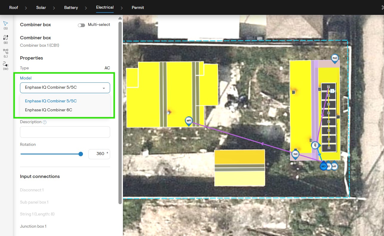
Electrical design - Select AC combiner box model.
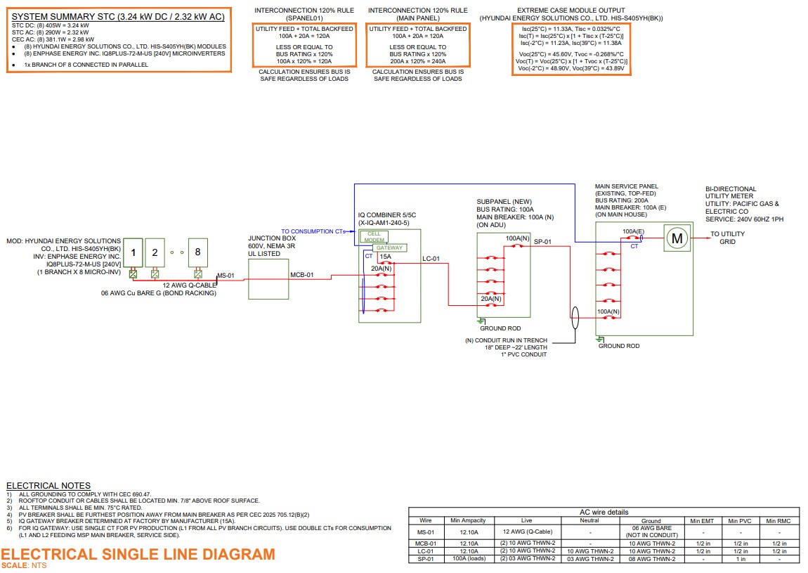
SLD - PV only design with IQ combiner 6C.
PV and Battery Designs
Grid-Tied Mode
This mode supports PV and battery designs for grid-tied systems.
- On the Battery Design tab, toggle On the grid-tied mode.
- Select the battery you want to use.
- On the Electrical Design tab, add a combiner box. The Connect battery option will be enabled by default.
- If needed, enable a battery disconnect.
- Place the main panel box and connect all components.
- Complete the circuit design and generate the SLD.
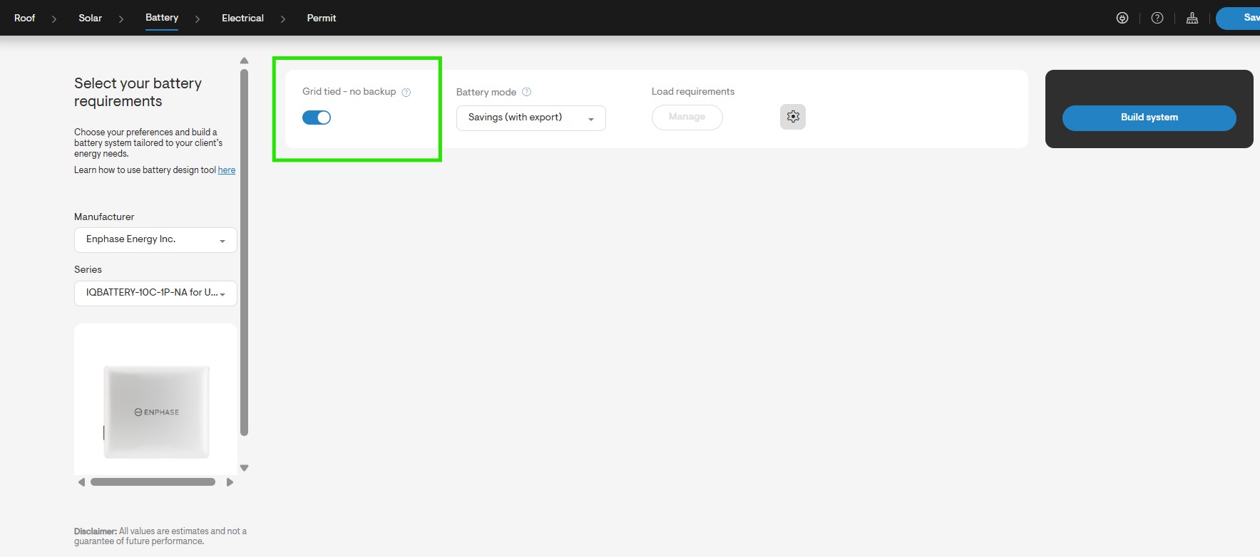
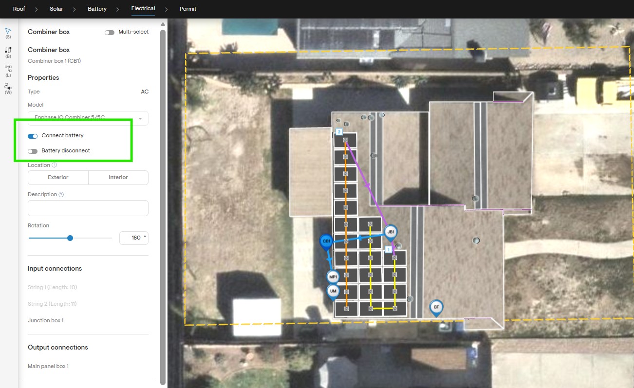
Electrical design - Battery disconnect option.
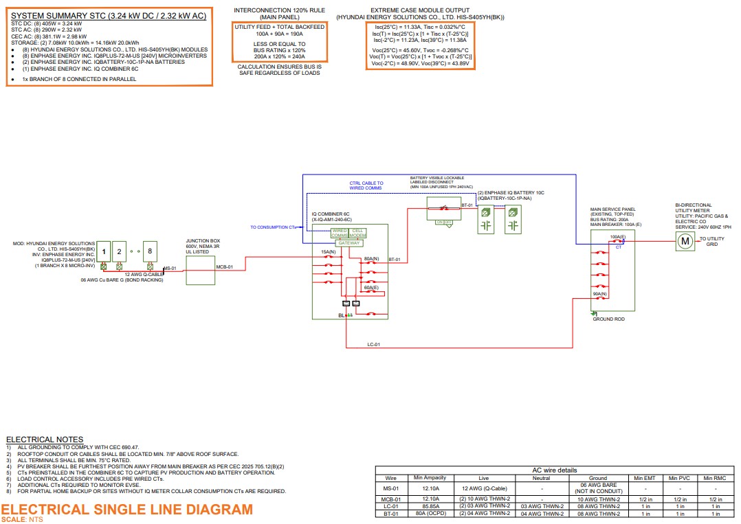
SLD - PV + Battery design in Grid-tied mode.
Full Home Backup with IQ Meter Collar
To generate SLD for full-home backup systems using an IQ Meter Collar.
- On the Electrical Design tab, place the main service panel box.
- Under its properties, the "IQ meter collar integrated with utility meter" will be selected automatically.
- If needed, you can choose "IQ meter collar integrated with discrete meter pan" from the dropdown.
- Connect all components, complete the circuit design, and generate the SLD.
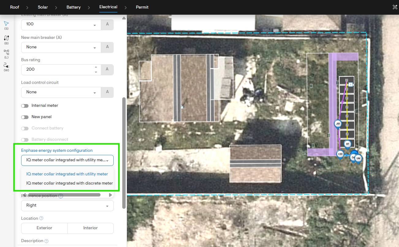
Electrical design - Select Enphase energy system configuration option.
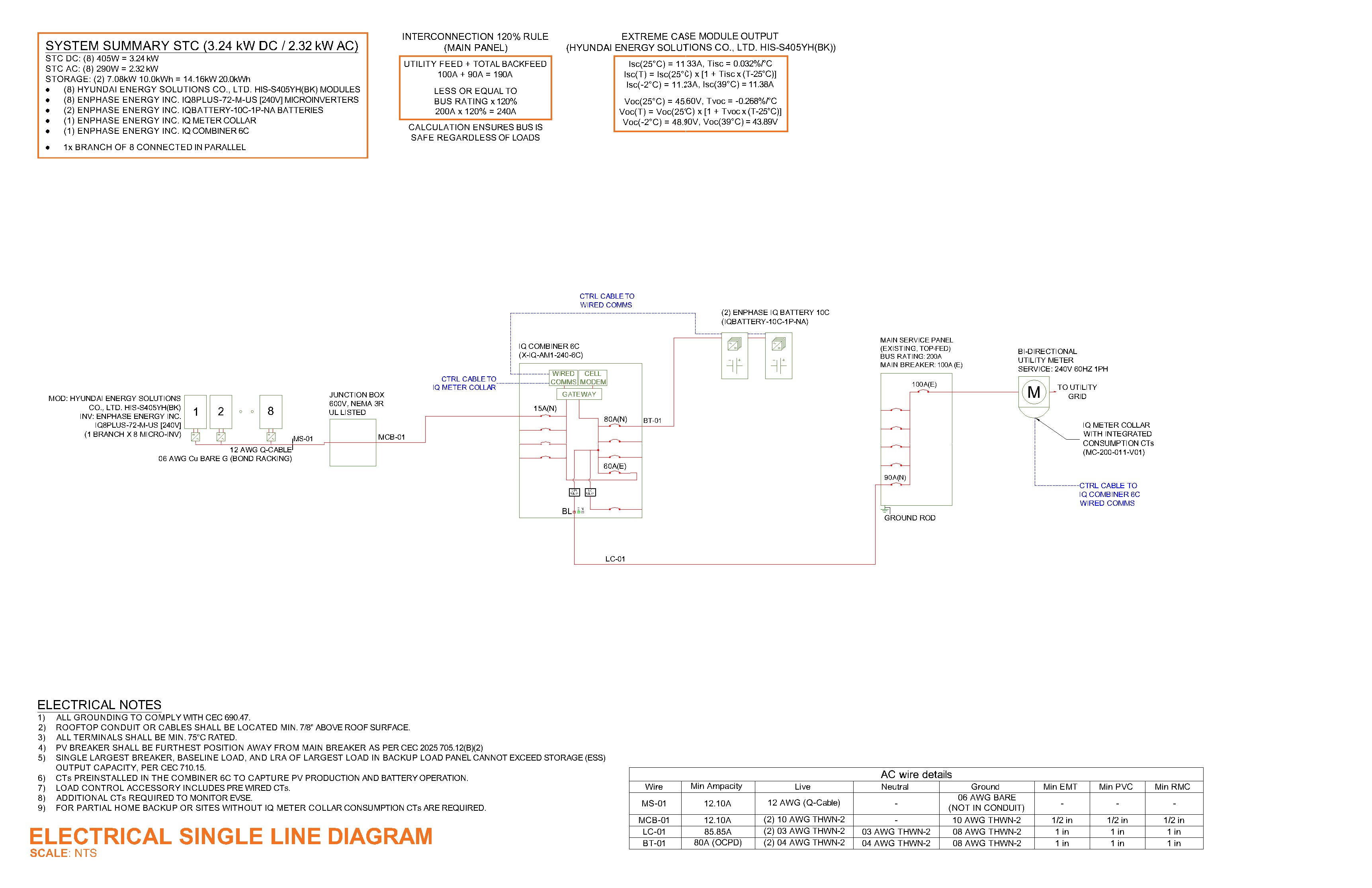
SLD - PV + Battery design in full home backup mode using IQ meter collar.
Partial Home Backup with IQ Meter Collar
To generate SLD for partial-home backup systems with an IQ Meter Collar integrated with a discrete meter pan.
- On the Electrical Design tab, place a sub-panel box.
- If the sub-panel has a main breaker, toggle On the main breaker option in the properties section and enter the breaker rating. If it doesn't have a main breaker, provide the panel load rating.
- The "IQ meter collar integrated with discrete meter pan" will be automatically selected.
- Place the main service panel, connect all components, and complete the design to generate the SLD.
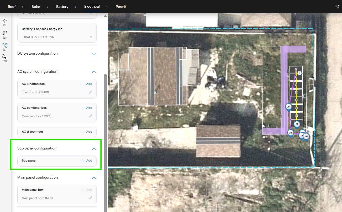
Electrical design - Place sub panel box.
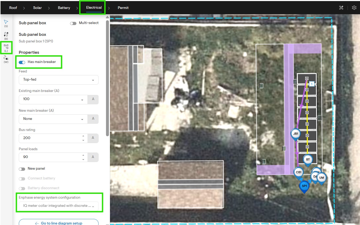
Electrical design - Sub panel box properties.
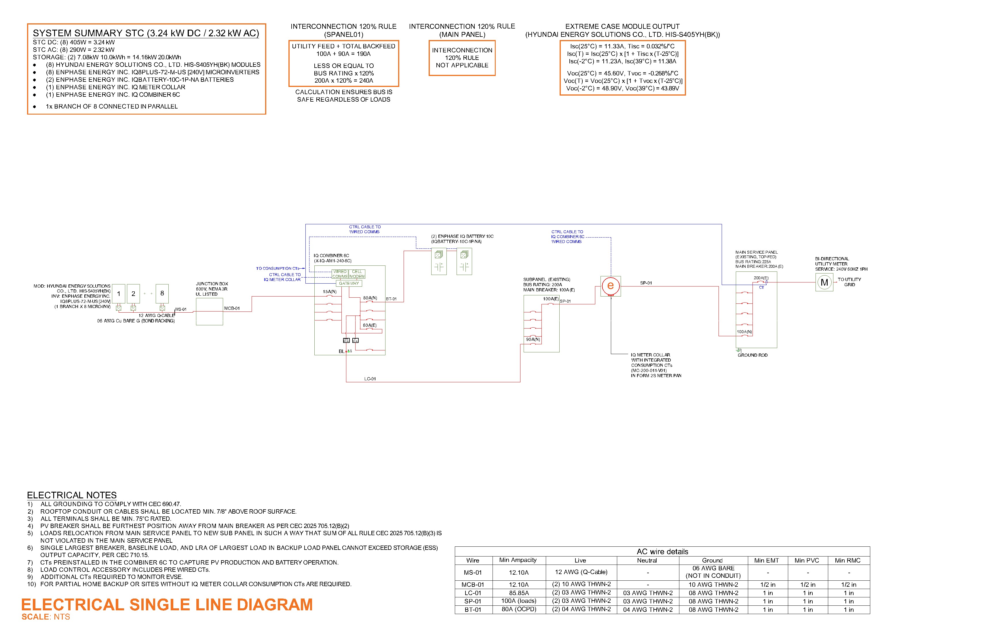
SLD - PV + Battery design in partial home backup mode using IQ meter collar integrated with discrete meter pan.
Using the IQ System Controller 3/3G/3M
To generate SLD for for full-home backup designs using the IQ System Controller 3/3G/3M.
- On the Electrical Design tab, place the main panel box.
- In the properties section of the main service panel, toggle On the Connect battery option.
- Enable a battery disconnect if needed.
- Choose the appropriate system controller configuration from the dropdown menu of Enphase energy system configuration field .
- Connect all components, complete the circuit design, and generate the SLD.
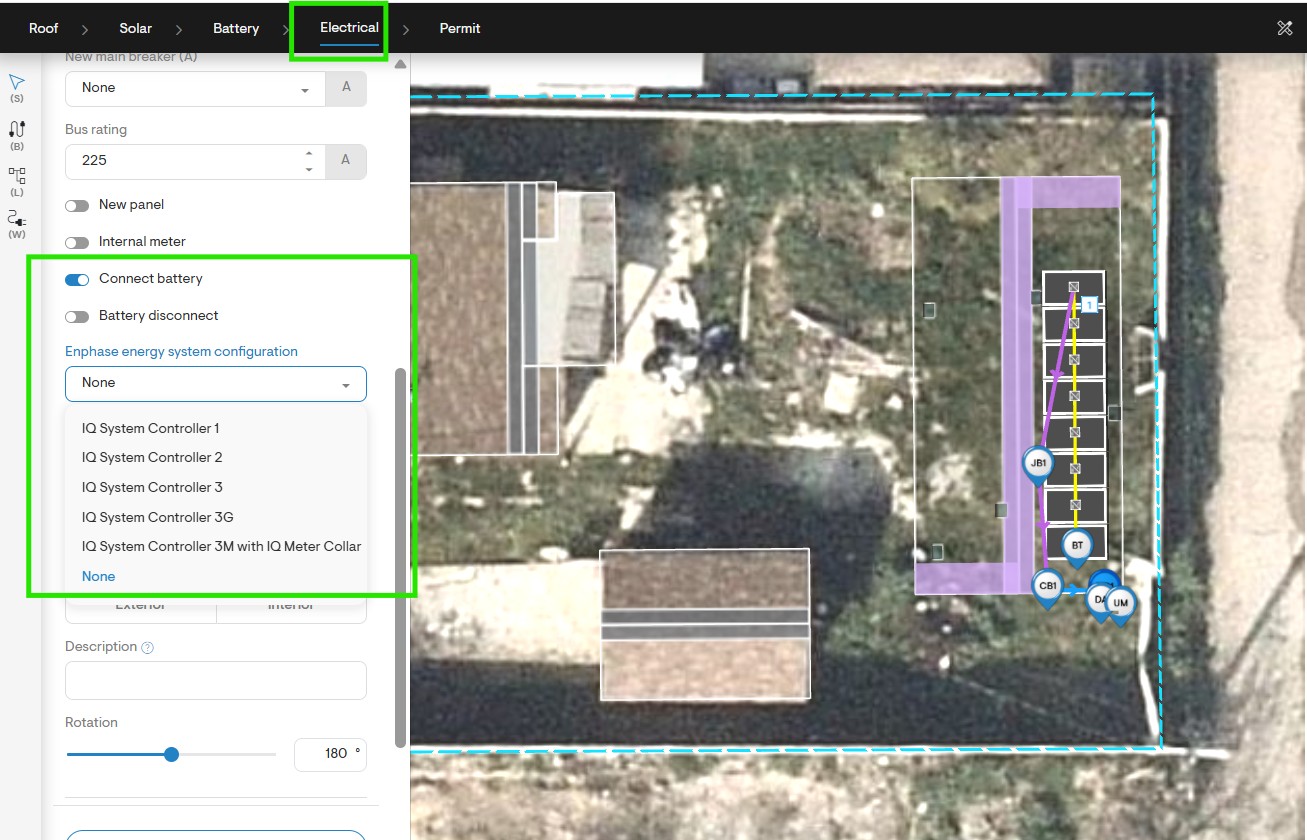
Electrical design - main service box properties.
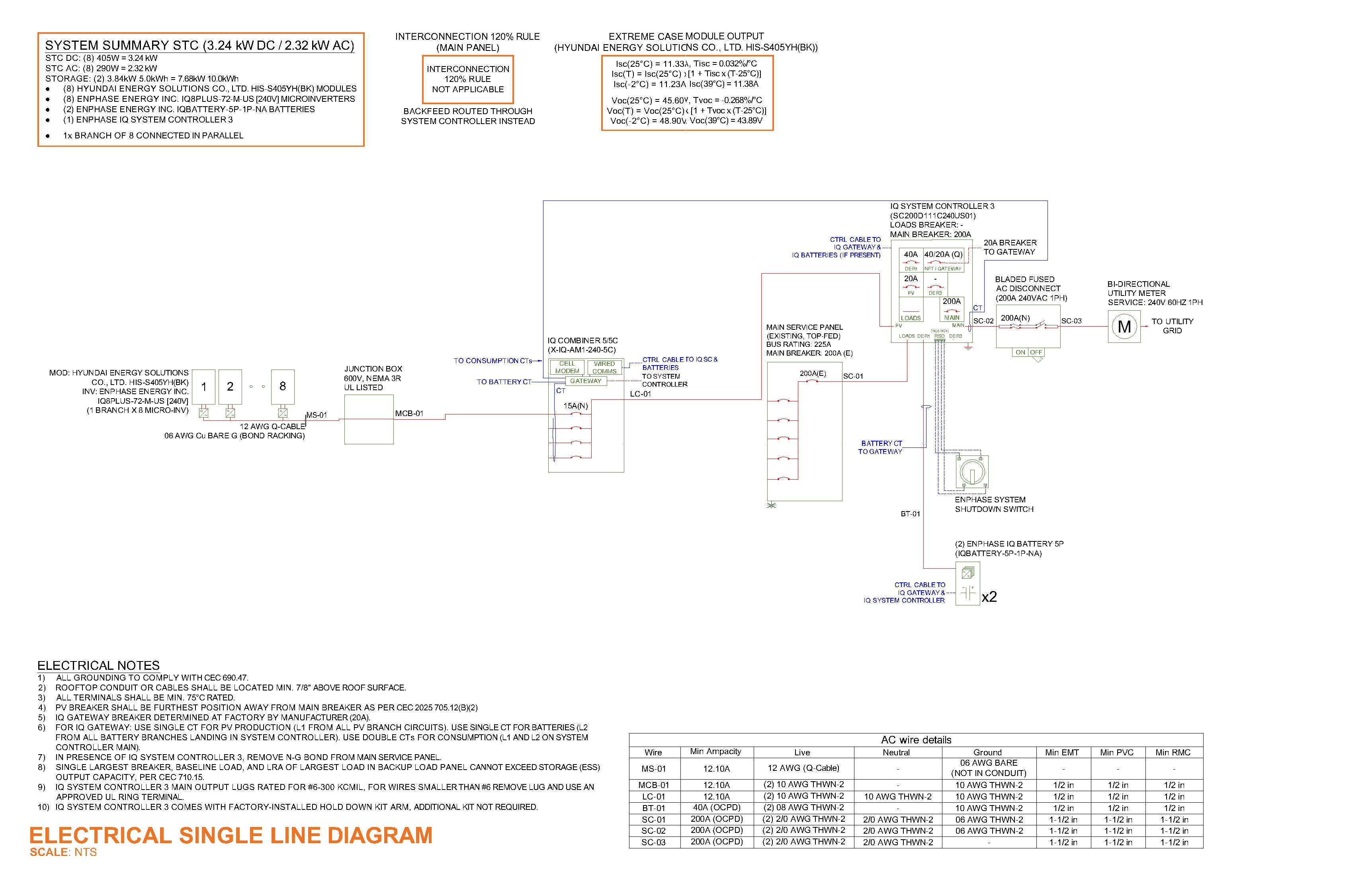
SLD - PV + Battery design using IQ System controller.
Specialized Designs
Line side connection
To generate SLD with line side connection interconnection method:
- On the Electrical Design tab, place a main service panel box.
- In the properties section, select Line-side connection option under Tie-in field.
- Connect all components, complete the circuit design, and generate the SLD.